

| A foundry contains a process for separating the runner and riser from castings. Until about a quarter of a century ago, the work had been conducted mainly by hammer and been very heavy work requiring a lot of physical labor. In those days, people in the industry used to say that, even if you introduced a high-performance molding machine, resulting in productivity, that process of separation would often slow it down. Born out of the necessity to combat these problems was the Gate Pecker. It was initially not designed for sale. The machine born in a foundry in response to the pressing need spread widely by word of mouth later on, winning the confidence of other foundries. The Gate Pecker is now active in lots of foundries as an effective and handy tool for higher productivity and sustainability. |
| The machine consists of a main unit (tool) section, hydraulic unit section, and hoisting section. |
| Features |
|
| MODEL ・ SPECIFICATIONS |
| ● MAIN UNIT(TOOL) |
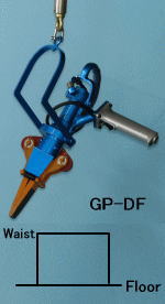
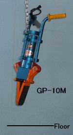
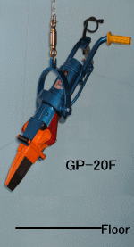
| Layout | Waist Level | Floor Level | ||
| Type | Standard Type | Flexible Type | Standard Type | Flexible Type |
| Photo |  |
 |
 |
 |
| Feature | One Hand Operation (-MN) | Vertical and Swivel Motion | Simple Structure, Easy Handling |
Vertical and Swivel Motion |
| Models | GP-MN,-DM,-5VS | GP-DF,-5FK,(-10S) | GP-5LV,-10M,(-20) | GP-10F,-20F |
| * | Layout | : | Use the waist level line to separate castings at the waist level. Use the floor level line to do so at your feet. |
| * | Flexible type | : | The bill section moves flexibly in vertical and swivel motion, thus being user-friendly. The flexible type is suitable if the bills do not have constant opening widths of bill (narrow, wide). |
| ◆ SPECIFICATION [MAIN UNIT] [HOISTING] |
| Main Unit | Hoisting | |||||||||||||||
| Model 1) |
Work ‐level |
Type | Length (㎜) |
Weight (㎏) |
Breaking Power 2) (t) |
Opening Width of Bill | Size of Bill | Jack | Features | Hose | Balancer | Trolley | ||||
| Min (㎜) |
Max (㎜) |
Length (㎜) |
Width (㎜) |
Angle (°) |
Ton× Stroke(㎜) |
WR 3) |
BN 4) |
Dia×L (㎜ø×m) |
Min~Max (㎏) |
Max (㎏) |
||||||
| GP-MN | Waist | Standard | 330 | 5 | 5.5 | 10→24 | 28→42 | 70 | 26 | 14 | 2.0×60 | ― | ― | 5×6 | 4.5~9 | 60 |
| GP-DM | Waist | Standard | 400 | 8 | 9 | 11→32 | 35→56 | 100 | 35 | 14 | 3.5×80 | ― | ― | 5×6 | 4.5~9 | 60 |
| GP-DF | Waist | Flexible | 600 | 11 | 9 | 11→32 | 35→56 | 100 | 35 | 14 | 3.5×80 | ― | ― | 5×6 | 9~15 | 60 |
| GP-5VS | Waist | Standard | 570 | 15 | 14 | 12→42 | 47→77 | 130 | 40 | 16 | 5.5×100 | ○ | ○ | 6×6 | 15~22 | 60 |
| GP-5FK | Waist | Flexible | 640 | 17 | 14 | 12→42 | 47→77 | 130 | 40 | 16 | 5.5×100 | ― | ○ | 6×6 | 15~22 | 60 |
| GP-5LV | Floor | Standard | 750 | 15 | 14 | 12→42 | 47→77 | 130 | 40 | 16 | 5.5×100 | ○ | ○ | 6×6 | 15~22 | 500 |
| GP-10S | Waist | (Flexible) | 580 | 25 | 27 | 14→46 | 66→98 | 180 | 50 | 17 | 10.5×100 | ○ | ○ | 9×6 | 22~30 | 500 |
| GP-10F | Floor | Flexible | 820 | 33 | 27 | 14→46 | 66→98 | 180 | 50 | 17 | 10.5×100 | ― | ― | 9×6 | 30~40 | 500 |
| GP-10M | Floor | Standard | 770 | 25 | 27 | 14→46 | 66→98 | 180 | 50 | 17 | 10.5×100 | ○ | ○ | 9×6 | 22~30 | 500 |
| GP-20 | Floor | Housing | 750 | 45 | 40 | 18→46 | 90→118 | 180 | 50 | 24 | 20.0×100 | ― | ― | 9×6 | 40~50 | 500 |
| GP-20F | Floor | Flexible | 950 | 54 | 40 | 18→46 | 90→118 | 180 | 50 | 24 | 20.0×100 | ― | ― | 9×6 | 50~60 | 500 |
| 1) | Model | : | For old models, see All Models. For model selection, see Model Selection. |
| 2) | Breaking Power | : | as 70MPa. |
| 3) | WR/〇 | : | with Wear Ring. |
| 4) | BN/〇 | : | Slider Fastend with Two Cap Screws and Double Nuts. |
| ● HYDRAULIC UNIT | ◆ SPECIFICATION [Hydraulic unit] |
|
|
||||||||||||||||||||||||||||||||||||||||||||||||||||||||
| 5) | Optional Voltage | : | 380V,415V |
| 6) | Option | : | The standard type and high speed type oil coolers and oil cleaners are optional. |
| 7) | Combinations | : | These hydraulic units can be connected and combined with all main units. Note, however, that a compact type combined with a large model (GP-20 or GP-20F) slows down the work. |
|
[Note] |